title: Report - NSV semestral project subtitle: I2C core + counter on SSD1306 display author: František Boháček documentclass: scrartcl date: January 20, 2023 defaults:
- defaults.yaml csl: bib.csl references:
- type: incollection
id: i2c-spec
title: "I2C-bus specification and user manual"
author: "NXP"
URL: https://www.nxp.com/docs/en/user-guide/UM10204.pdf
issued:
year: 2021
month: 1
output:
rmarkdown::pdf_document:
fig_caption: yes
includes:
in_header: figure_placement.tex
header-includes:
- |
pandoc-latex-environment: noteblock: [note] tipblock: [tip] warningblock: [warning] cautionblock: [caution] importantblock: [important]\usepackage{awesomebox} \usepackage{pdflscape} \usepackage{rotating}
#Introduction
This project aims to implement I2C core, both master and slave. Then, a scenario will be implemented to verify I2C is working on real FPGA and not only in simulation. The master will be tested by showing three numbers as a counter on SSD1306 with I2C interface.
I2C might be used for communication with multiple devices. It supports up to 3.4 Mbps speeds (High-speed mode). [-@i2c-spec] That is sufficient for many applications. I2C is used often, most microcontrollers include I2C hardware support as well.
There can be multiple devices on the bus
with just two wires, called sda and scl. Every slave
gets an address assigned, and the master can select the device
by transmitting the address corresponding to selected slave.
There can be multiple masters on the bus. If both start
a transaction at the same time, there is an arbitration.
The first master that detects incorrect value of sda
loses, and the other one gets to make the transaction.
#Manual
The project consists of multiple VHDL libraries.
The most important one is perhaps the i2c library located
in the src/i2c folder. This library uses the utils library located
in src/utils. Blocks from the utils library are not documented here
for their simplicity. It contains a open_drain_buffer, a metastability_filter, a pulse_delay
for delaying a pulse, sync_edge_detector for detecting rising or falling
edges on a signal synchronous to a clock.
There is ssd1306 library with two entities for testing out the I2C master entity with
SSD1306 display. One of these makes the display full on, the other has a counter that
counts every second.
Last, but not least there is mcu_slave library that contains two
entities. One of these just respondes with a simple count when read I2C
requested. The other entity is behaving as a register reader/writer,
with 20 registers. The first written byte is treated as an address.
Other read bytes are consecutive reads from the registers. Other
writes are treated as consecutive writes to the registers.
::: note The port names follow a specific pattern.
Inputs have _i suffix, whereas outputs have _o suffix.
When an input or output is active low, it's suffix will include n at the end.
:::
#Simulation
For simulating, VUnit framework has been used.
It comes with a Python library that makes it easy to run the testbenches.
The starting script is located in the root of the project, and called run.py.
It also comes with a VHDL library that adds some enhancements for the testing and
communication with the Python side.
All non-trivial entities were tested in simulation with various use cases. Every entity was tested by itself, and then, tests of the top level entities were performed as well. RTL I2C master has been tested by having a simple behavioral I2C slave implemented. RTL I2C slave by having simple I2C master implemented.
All of the tests are checking if the result is correct by themselves. It's thus not required to go into the waves and check as a person. This means it's possible to make some changes, and check whether the changes have broken something very fast.
The libraries for simulation include _tb suffix. There is a testbench library for every
design library.
#SSD1306 display counter
The SSD1306 display is a 128x64 display that supports various interfacing methods such as I2C.
The characters used for the counter were obtained from a monochrome bitmap font font8x8.
The display first has to be initialized, the RAM nulled, and then data might be sent then. The display supports three addressing modes, page, horizontal, and vertical. It has multiple pages, each page consists of 8 rows on the display. The horizontal addressing mode is exploited for drawing characters/numbers. The character can be written in one go, and after a character is written, another one can be written correctly without adjusting the cursor. This makes it possible to draw characters without storing them in some kind of buffer on the master device.
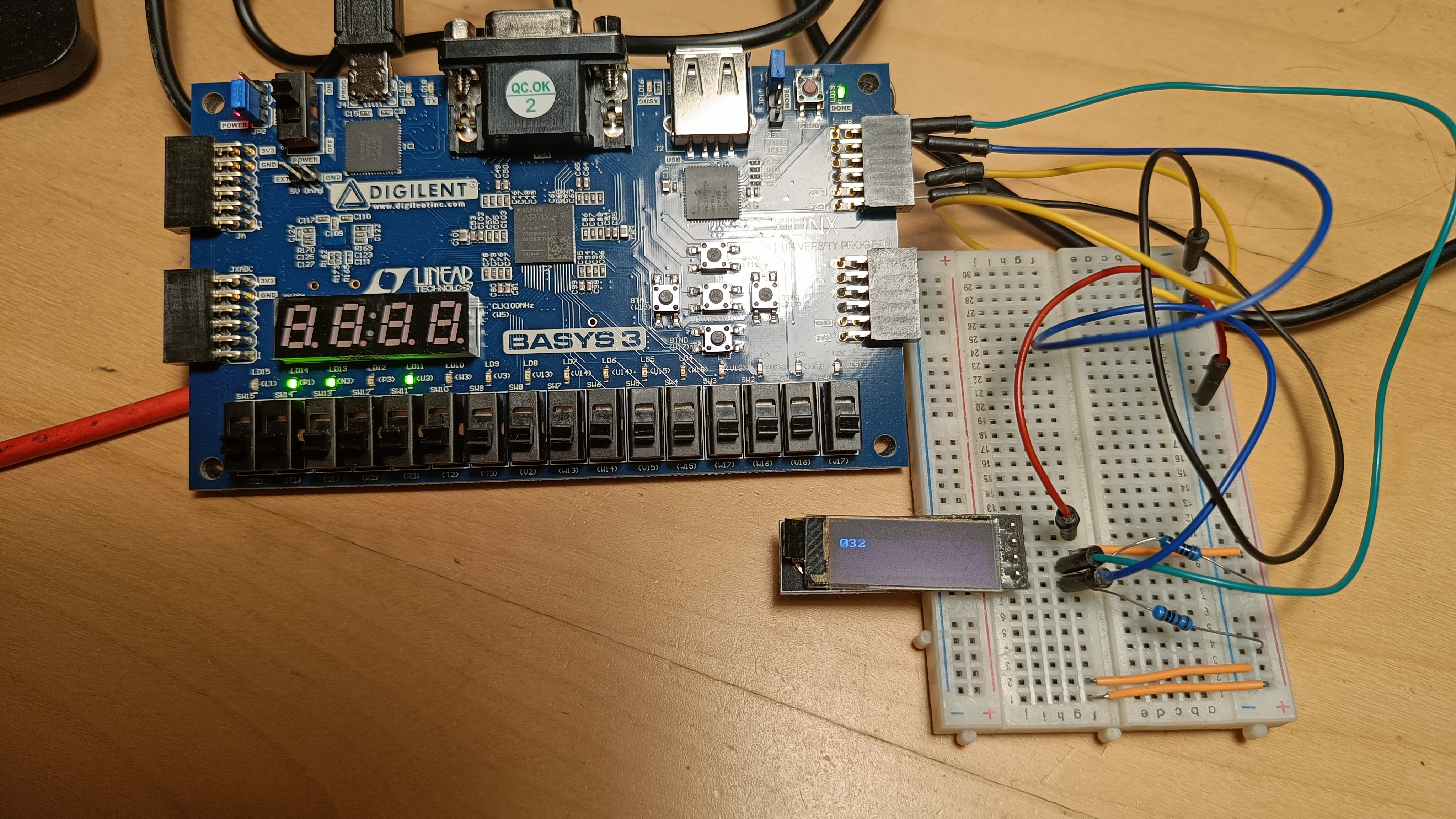
See the following figure showing the setup with Basys 3 board with SSD1306 counter entity connected to the SSD1306.
The top level entity consists of three main entities. One of those is for a BCD counter, another for FSM for controlling the SSD1306 display, and data that are being sent to it, and the last for I2C master.
There are also three supporting entities, two open drain buffers
for scl and sda. The last one is for treating metastability of the
reset.
The following page shows the diagram of the top level entity for SSD1306 counter exported from Vivado.
\pagenumbering{gobble} \begin{landscape} \begin{sidewaysfigure}[ht] \centering
\hspace*{-5cm} \vspace{-3cm} \includegraphics[angle=180, width=850pt, trim=-5cm 0 0 -5cm]{./img/ssd1306_counter_schematic.pdf} \caption{SSD1306 counter top level diagram}
\end{sidewaysfigure} \end{landscape} \pagenumbering{arabic}
#I2C
The implementation consists of two separate top level entities, one of those is used for master entity and the other for slave entity.
The sda and scl lines are controlled by sda_enable and scl_enable signals.
Having these set to high means the line should be pulled down. There is also sda and
scl inputs that should get the actual values of the GPIO.
An open_drain_buffer entity should be used
to connect the input and enable output to the actual pad.
Both master and slave entities share the rx and tx data interfaces.
The difference is that master has signals for requesting a new transaction,
but the slave waits for a start condition to start receiving/transmitting.
#Entity master
The master entity is a top level entity for using the I2C core as a master. It connects all of the blocks for a functioning I2C master.
The entity has three control inputs start, stop, and run.
Run should be high when the master is operating. Setting start high
will generate a start condition when possible. Setting stop high
will generate a stop condition when possible.
Both start and stop should be set high for just one cycle.
When setting both start and stop high at the same time,
one byte will be transmitted or received, and then stop condition
generated.
The entity supports arbitrary scl speeds. But only one can be chosen
for instance, via generic argument. The generator always makes sure the
scl is stable for at least SCL_MIN_STABLE_CYCLES clock cycles.
Table: Ports of master entity
| Name | Type | Description |
|---|---|---|
| clk_i | std_logic | Clock input |
| rst_in | std_logic | Asynchronous reset (active low) |
| slave_address_i | std_logic_vector[7] | Address of the slave to choose |
| generate_ack_i | std_logic | Whether to generate acknowledges on received data |
| expect_ack_i | std_logic | Whether to expect acknowledges on transmitted data |
| rx_valid_o | std_logic | rx_data are valid |
| rx_data_o | std_logic_vector[8] | Received data |
| rx_confirm_i | std_logic | Confirm read of rx_data to receive next |
| tx_ready_o | std_logic | tx_data may be received |
| tx_valid_i | std_logic | tx_data are valid |
| tx_data_i | std_logic_vector[8] | Data to transmit |
| tx_clear_buffer_i | std_logic | Clear transmit buffer (unsent data) |
| err_noack_data_o | std_logic | Got NACK when transmitting |
| err_noack_address_o | std_logic | Got NACK on first byte with address |
| err_arbitration_o | std_logic | Got unexpected value on sda |
| err_general_o | std_logic | Other errors, like unexpected start cond |
| stop_i | std_logic | Generate stop condition when possible |
| start_i | std_logic | Generate start condition when possible |
| run_i | std_logic | |
| rw_i | std_logic | Read or write transaction (R = 1) |
| dev_busy_o | std_logic | Master device is currently busy |
| bus_busy_o | std_logic | Bus is busy (but master is not) |
| waiting_o | std_logic | Waiting for data on transmit or for read confirm |
| sda_i | std_logic | I2C sda line |
| scl_i | std_logic | I2C scl line |
| sda_enable_o | std_logic | Pull sda low |
| scl_enable_o | std_logic | Pull scl low |
Table: Generic arguments of master entity
| Name | Type | Default value |
|---|---|---|
| SCL_FALLING_DELAY | natural | How many clock cycles to wait |
after scl falling to set sda |
||
| SCL_MIN_STABLE_CYCLES | natural | Minimum clock cycles to keep scl stable |
The following page contains the diagram of the I2C master entity
along with all components.
\pagenumbering{gobble} \begin{landscape} \begin{sidewaysfigure}[ht] \centering
\hspace*{-5cm} \vspace{2cm} \includegraphics[angle=180, width=700pt, trim=0 0 0 0]{./img/i2c_master_schematic.pdf} \caption{SSD1306 counter top level diagram}
\end{sidewaysfigure} \end{landscape} \pagenumbering{arabic}
#Entity slave
Slave entity is a top level for I2C slave.
It outputs the current state (such as bus busy, device busy, r/w) upon receiving commands from the master.
Table: Ports of slave entity
| Name | Type | Description |
|---|---|---|
| clk_i | std_logic | Clock input |
| rst_in | std_logic | Asynchronous reset (active low) |
| address_i | std_logic_vector[7] | Address of the slave |
| generate_ack_i | std_logic | Whether to generate ack on every read |
| expect_ack_i | std_logic | Whether to expect acknowledges on transmitted data |
| rx_valid_o | std_logic | rx_data are valid |
| rx_data_o | std_logic_vector[8] | Received data |
| rx_confirm_i | std_logic | Confirm data of rx_data to receive next |
| rx_stretch_i | std_logic | Allow stretching when buffer full |
| tx_ready_o | std_logic | tx_data may be received |
| tx_valid_i | std_logic | tx_data are valid |
| tx_data_i | std_logic_vector[8] | Data to transmit |
| tx_stretch_i | std_logic | Allow stretching on transmitting (no data) |
| tx_clear_buffer_i | std_logic | Clear transmit buffer (unsent data) |
| err_noack_o | std_logic | Got NACK when transmitting |
| err_sda_o | std_logic | Got unexpected value on sda |
| rw_o | std_logic | Read or write transaction (R = 1) |
| dev_busy_o | std_logic | Master device is currently busy |
| bus_busy_o | std_logic | Bus is busy (but master is not) |
| waiting_o | std_logic | Waiting for data on transmit or for read confirm |
| sda_i | std_logic | I2C sda line |
| scl_i | std_logic | I2C scl line |
| sda_enable_o | std_logic | Pull sda low |
| scl_enable_o | std_logic | Pull scl low |
Table: Generic arguments of slave entity
| Name | Type | Default value |
|---|---|---|
| SCL_FALLING_DELAY | natural | How many clock cycles to wait after |
scl falling to set sda |
The following page contains the diagram of the I2C slave entity
along with all components.
\pagenumbering{gobble} \begin{landscape} \begin{sidewaysfigure}[ht] \centering
\hspace*{-5cm} \vspace{2cm} \includegraphics[angle=180, width=700pt, trim=0 0 0 0]{./img/i2c_slave_schematic.pdf} \caption{SSD1306 counter top level diagram}
\end{sidewaysfigure} \end{landscape} \pagenumbering{arabic}
#Common
All of the blocks responsible for receiving or sending data
should get the scl state from the input going to the FPGA/ASIC,
the same goes for sda.
This makes sure that features such as scl stretching or arbitration
are supported. If scl from scl_generator were to be used, there
would be no possibility to detect either one of those.
:::note
Some of the entities accept delayed falling pulse of scl.
This is to make sure sda is changed after scl is indeed
low. If sda were to be changed right away, it's possible there would
be a device that would detect start or stop condition when
there is actually no condition.
:::
#Entity address_generator
Address generator is responsible for sending
address when requested. It's used in the I2C master
to select a slave. Currently it supports only 7 bit addresses.
It checks ACK as well, and outputs noack_o for NACK.
It also checks the sda level when sending to detect
arbitration loss.
Table: Ports of address_generator entity
| Name | Type | Description |
|---|---|---|
| clk_i | std_logic | Clock input |
| rst_in | std_logic | Synchronous reset (active low) |
| address_i | std_logic_vector[7] | The address to send |
| rw_i | std_logic | R/W to send (R = 1) |
| store_address_rw_i | std_logic | When to store address and rw |
| start_i | std_logic | Start sending address |
| scl_rising_i | std_logic | scl rising pulse |
| scl_falling_delayed_i | std_logic | scl falling pulse delayed |
| sda_enable_o | std_logic | Keep sda low |
| sda_i | std_logic | Current sda level |
| noack_o | std_logic | Did not get acknowledge |
| unexpected_sda_o | std_logic | sda detected at scl rising edge is wrong. |
| (Arbitration lost) | ||
| done_o | std_logic | Address sent |
#Entity address_detector
Address detector looks at the received data to check if the address matches the address of the slave. Currently it supports only 7 bit addresses. It supports sending ACK after address received.
Table: Ports of address_detector entity
| Name | Type | Description |
|---|---|---|
| clk_i | std_logic | Clock input |
| rst_in | std_logic | Synchronous reset (active low) |
| address_i | std_logic_vector[7] | The address to detect |
| store_address_i | std_logic | When to store the address to buffer |
| scl_rising | std_logic | scl rising pulse |
| scl_falling_delayed_i | std_logic | scl falling pulse delayed |
| sda_enable_o | std_logic | Keep sda low |
| sda_i | std_logic | Current sda level |
| start_i | std_logic | Start detecting address with next scl |
| rw_o | std_logic | Detected R/W value |
| success_o | std_logic | Address matching. rw set |
| fail_o | std_logic | Address not matching |
#Entity rx
Receiver entity is responsible for receiving data from the
data bit line (sda), and delivering the bytes received.
It's not meant to be used as detector of the address, that is
what address_detector is for.
The entity supports scl stretching. When the data are not yet
read (that should be signaled by confirm_read_i), it will stretch
the scl to prevent loss of data. The data are stored in a separate buffer
when full data are received. This makes it possible to start receiving next byte
immediately without having to wait for read from another entity. However, if the
receive buffer gets full with second byte, there is need for the stretching.
For master, this means scl is not generated, for slave it
means it's held down even though the master is trying to let go
to get high level.
The entity is also responsible for acknowledging the received data when
generate_ack_i is set.
Table: Ports of rx entity
| Name | Type | Description |
|---|---|---|
| clk_i | std_logic | Clock input |
| rst_in | std_logic | Synchronous reset (active low) |
| start_read_i | std_logic | Read should be initiated on next scl |
| rst_i2c_i | std_logic | Reset only i2c logic, keep data |
| scl_rising | std_logic | scl rising pulse |
| scl_falling_delayed_i | std_logic | scl falling pulse, delayed |
| scl_stretch_o | std_logic | Keep scl low |
| sda_i | std_logic | Current sda level |
| sda_enable_o | std_logic | Whether to keep sda low |
| done_o | std_logic | Byte received, acknowledged |
| generate_ack_i | std_logic | Generate acknowledge after received |
| read_valid_o | std_logic | read_data are valid for reading |
| read_ready_o | std_logic | Ready for next transaction |
| read_data_o | std_logic_vector[8] | Read data |
| confirm_read_i | std_logic | Confirm data were read |
#Entity tx
Transmitter entity is responsible for transmitting data to the
data bit line (sda), and for storing the data to be sent next.
It's not meant to be used as generator/sender of the address, that is
what address_generator is for.
The entity supports scl stretching. When there are not any
data to be sent delivered yet, it will stretch
the scl.
For master, this means scl is not generated, for slave it
means it's held down even though the master is trying to let go
to get high level.
If wrong level is detected on the sda upon rising edge of scl,
the entity signals that in unexpected_sda_o.
The entity is also responsible for verifying acknowledge at the right time, and signaling that no acknowledge has been received.
Table: Ports of tx entity
| Name | Type | Description |
|---|---|---|
| clk_i | std_logic | Clock input |
| rst_in | std_logic | Synchronous reset (active low) |
| start_write_i | std_logic | Write should be initiated |
| rst_i2c_i | std_logic | Reset only i2c logic, keep data |
| clear_buffer_i | std_logic | Clear transmit buffer |
| done_o | std_logic | Data transmitted, and acknowledged |
| unexpected_sda_o | std_logic | sda value was wrong on scl rising |
| noack_o | std_logic | Did not get ACK |
| scl_rising | std_logic | scl rising pulse |
| scl_falling_delayed_i | std_logic | scl falling pulse, delayed |
| scl_stretch_o | std_logic | Keep scl low |
| sda_i | std_logic | Current sda level |
| sda_enable_o | std_logic | Keep sda low |
| ready_o | std_logic | Ready for new data |
| valid_i | std_logic | Data in write_data are valid |
| write_data_i | std_logic_vector[8] | Data to transmit |
#Entity scl_generator
Scl generator generates the scl while making sure
to keep the signal high or low (stable) for at least specified number of cycles.
It may send a signal when the scl cannot be set to high level,
that could signal a slave pulling down the line.
It supports single requests for falling or rising edges (used for startstop condition generation) as well as continuous (used for transmit/receive).
Table: Ports of scl_generator entity
| Name | Type | Description |
|---|---|---|
| clk_i | std_logic | Clock input |
| rst_in | std_logic | Synchronous reset (active low) |
| scl_i | std_logic | Current level of scl |
| scl_rising_i | std_logic | scl rising pulse |
| scl_falling_i | std_logic | scl falling pulse |
| gen_continuous_i | std_logic | Generate continuous scl clock |
| gen_rising_i | std_logic | Generate rising edge |
| gen_falling_i | std_logic | Generate falling edge |
| scl_enable_o | std_logic | Keep scl low |
| cannot_comply_o | std_logic | Cannot set scl high |
Table: Generic arguments of scl_generator entity
| Name | Type | Description |
|---|---|---|
| MIN_STABLE_CYCLES | natural | How many clock cycles to keep scl stable |
#Entity startstop_condition_detector
This entity detects either start or stop condition. It produces a pulse for duration of one clock cycle when either start or stop is detected.
Table: Ports of startstop_condition_detector entity
| Name | Type | Description |
|---|---|---|
| clk_i | std_logic | Clock input |
| sda_i | std_logic | Current sda level |
| scl_i | std_logic | Current level of scl |
| start_o | std_logic | Start condition detected |
| stop_o | std_logic | Stop condition detected |
#Entity startstop_condition_generator
Generates either start or stop condition. If the
scl has to be changed to different level, it generates
a request that should be handled by the scl_generator.
The generator should be able to generate the condition
from any starting state, as long as nothing else, including
the slaves, is not holding down either scl or sda.
If the sda has to be changed to be able to generate the condition,
scl is first requested to be pulled down, sda is changed,
after that, scl is requested to be high, and as last, the
sda is changed to generate the condition. Some of those might
be omitted according to the actual state of the sda and scl.
Table: Ports of startstop_condition_generator entity
| Name | Type | Description |
|---|---|---|
| clk_i | std_logic | Clock input |
| rst_in | std_logic | Synchronous reset (active low) |
| sda_i | std_logic | Current level of sda |
| scl_rising_i | std_logic | scl rising pulse |
| scl_falling_i | std_logic | scl falling pulse |
| scl_falling_delayed_i | std_logic | scl delayed falling pulse |
| sda_enable_o | std_logic | Keep sda low |
| start_condition_i | std_logic | Start condition detected |
| stop_condition_i | std_logic | Stop condition detected |
| gen_start_i | std_logic | Generate start condition |
| gen_stop_i | std_logic | Generate stop condition |
| req_scl_fall_o | std_logic | Request scl falling edge |
| req_scl_rise_o | std_logic | Request scl rising edge |
| early_condition_o | std_logic | Detected early condition (prior to generating ourselves) |
| done_o | std_logic | Requested condition generated |
| Name | Type | Description |
|---|---|---|
| DELAY | natural | How long to wait after each operation |
#Entity master_state
This entity is a FSM for the master entity.
It commands what should be done, such as generating
the address, receiving data, transmitting data, etc.
It also decides when to go to error state, and outputs an error
that is propagated through the master entity.
The errors are cleared upon next start request so that
it might be validated if there has been a new error for the
start request.
Inputs and outputs from other entities, should be explained by other entities well already.
#Entity slave_state
This entity is a FSM for the slave entity.
It commands what should be done, such as detecting
the address, receiving data, transmitting data, etc.
It also decides when to go to error state, and outputs an error
that is propagated through the slave entity.
The errors are cleared upon next start condition.
Inputs and outputs from other entities, should be explained by other entities well already.
#Block diagrams
 {width=50%}
 {width=50%}
 {width=50%}
 {width=50%}
 {width=50%}
 {width=50%}
 {width=50%}
 {width=40%}
 {width=50%}
 {width=50%}
 {width=50%}
#Conclusion
Both master and slave have been verified to be working in simulation and on an FPGA board. All found issues were solved, and when the issues were found on the FPGA, but not in simulation, a new testcase has been added to make sure the behavior is verified again if there were any changes made.
The components correctly monitor the bus even when they are not being used,
and output if the bus is busy or not. There are errors reported
in case something went wrong (wrong sda level, arbitration lost, etc.).
This should make the I2C components usable in real applications even if more masters
are incorporated on the bus.
There are some things that could be added or changed in the future, such as:
- 10 bit addressing support
- More error states (timeout)
- Multiple possible
sclfrequencies switchable after synthesis - Adding behavioral I2C master and I2C slave modules for simulation
The 10 bit addressing is not currently supported, although its support should not be hard
to implement. address_generator and address_detector entities interfaces make
it so that it would be sufficient to pospone setting done after the second byte
is received instead of the first one.
So far if the scl generator entity detects an error (that it cannot get the line high), it will produce a signal to say that, but this signal is not utilized in the FSM entity for the master. That means if the line stays low indefinitely (possibly due to a failing slave device), the master will become stuck without notifying the application about a possible problem.
The master entity supports only one frequency for scl for now.
That could be changed by passing in an array of values instead of one generic argument
for saying how many cycles to keep scl stable.
Then it could be chosen by an input port that would act as an index.
The simulation currently uses blocking procedures for testing.
These procedures are called from the top level simulation entities.
This makes it hard to test some of the features such as verifying whether
error signal became high at the correct scl edge.
It's also quite hard to test having multiple devices on the bus sending data simultaneously.
That could come in handy to test arbitration.
Both of these could be overcome by adding I2C behavioral modules, and instead of generating
the scl and sda from the top level testing entity, they would be generated
by these behavioral models.
The top level entity would just notify the behavioral models to start generating or expect the
given transaction.